Front Panel
The Time Machine V3 front panel contains all the controls and indicators you need for race day operation.
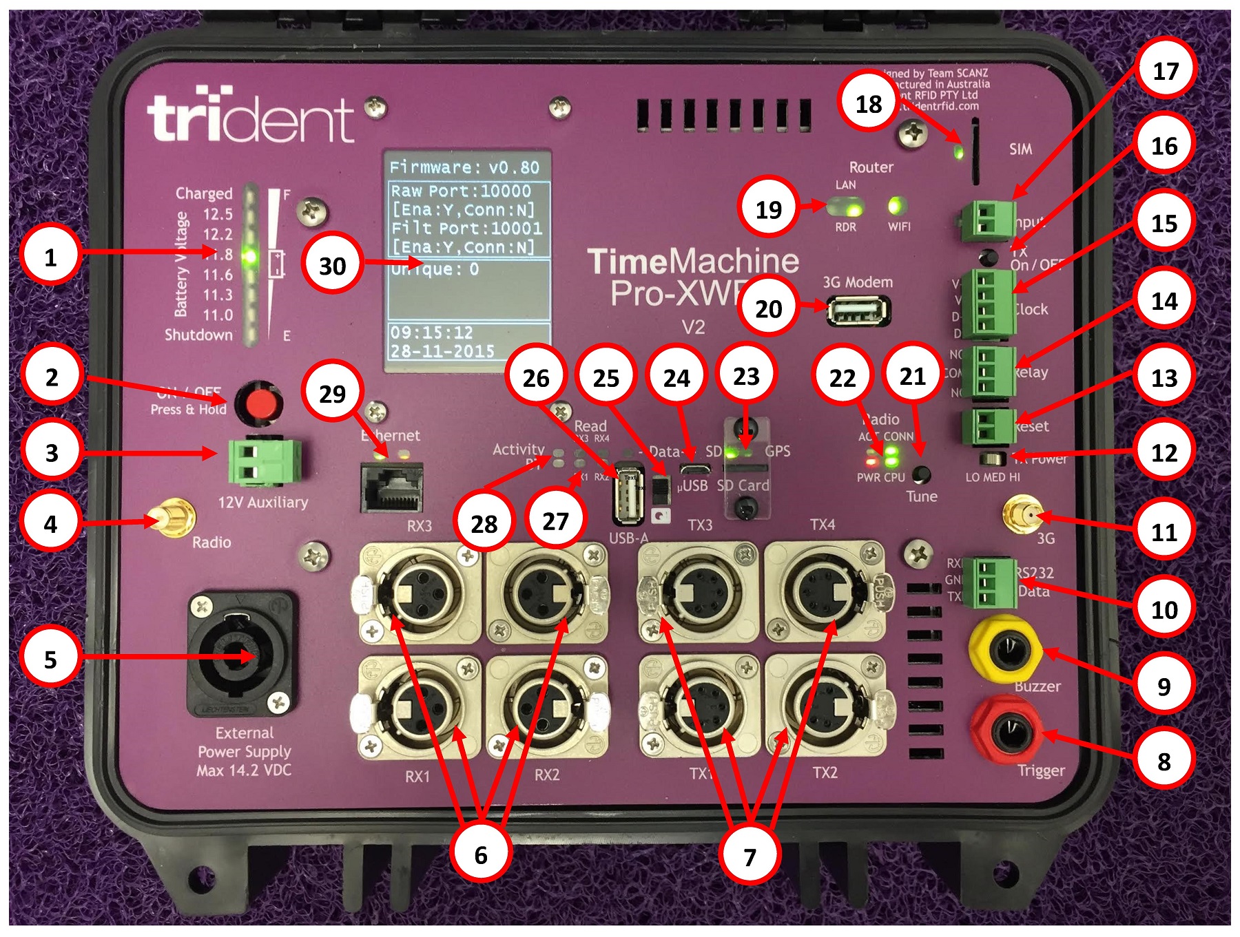
Key Components
Power Section
- Battery Voltage Indicator
-
Shows current battery charge level. Monitor this to ensure adequate power throughout the race.
- Power Button
-
Turns the unit on and off.
- External Power Socket
-
Connect external power supply for extended operation or charging.
Network Section
- Ethernet RJ45 Socket
-
Connect network cable to laptop. The V3 has dual ethernet ports.
- Router Status Indicators
-
Show WiFi/network connectivity status.
Timing Section
- Receive Loop Sockets
-
Connect antenna receive cables here.
- Transmit Loop Sockets
-
Connect antenna transmit cables here.
- Transmit Tune Button
-
Adjusts transmission power (low/medium/high). Typically preset by advanced staff.
Operator Focus Areas
For race day operations, focus on these areas:
| Component | Why It Matters |
|---|---|
Battery/Power Indicator |
Ensure you have power throughout the race |
LCD Status Display |
Verify network and logging are active |
Tag Activity Indicators |
Confirm chips are being detected |
Network Status |
Verify connection to laptop |
Handling
-
Do not cover ventilation areas
-
Keep the unit dry
-
Position where you can see the LCD display
-
Protect from direct sunlight in extreme heat
See Status Indicators for detailed information on interpreting the display.